
Basic Roamer AR Version 2 Features
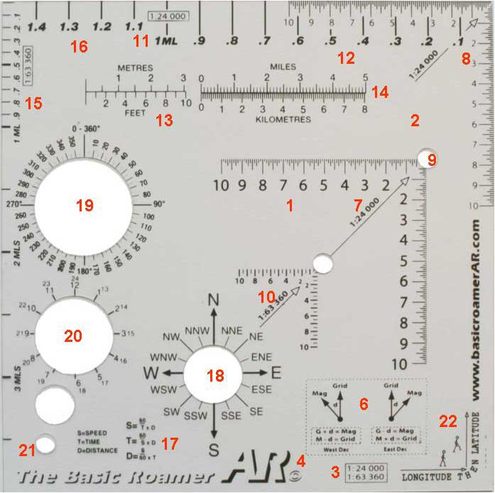
1. Precision engineered
2. Very clear for easy map reading
3. Based on scale of 1:24,000 and 1:63,360
4. Protected by copyright
5. All information is parallel and easy to read
6. Magnetic declination conversion chart
7. 1:24,000 UTM Grid
8. Primary 1:24,000 UTM Grid without CP hole
9. 100 Meter diameter cutout on 1:24,000 UTM grid for CP location
10. 1:63,360 UTM Grid for 1inch to 1 mile maps
11. 1.5 mile scale at 1:24,000
12. 1/10th mile distance measuring scale at 1:24,000 scale
13. Meters to feet/feet to meters conversion scale
14. Miles to kilometers/kilometers to miles conversion scale
15. 1:63,360 distance measuring scale with 1/10th increments on first mile
16. 1:24,000 distance measuring scale
17. Speed, time and distance calculations
18. Points of compass circle
19. Degrees of circle to 0 to 360
20. 12 & 24 hour clock face
21. Hole for neck cord
22. Helpful Basic Roamer AR logo as Longitude and Latitude hint
23. Complete instructions on major features
1. Precision engineered
The Basic Roamer AR has been precision engineered to be very accurate with UTM markings down to 10 meters. This is
more accurate than most other UTM plotting tools that only have 20 meter markings.
2. Very clear for easy map reading
The material that the Basic Roamer AR is constructed from is very clear to allow easy reading of the map detail below.
Based on scale of 1:24,000 and 1:63,360
The Basic Roamer AR is currently based on the 1:24,000 and 1:63:360 (1Ó per Mile) scales. These are the most common
scales used in Adventure Racing and the Basic Roamer AR enables plotting, measuring and conversion of these scales.
4. Protected by copyright
The Basic Roamer products are protected by copyright.
5. All information is parallel and easy to read
The information on the Basic Roamer AR is formatted parallel to allow easy use and fast navigation assistance. There is
no need to keep spinning the Basic Roamer AR around to find the information you are looking for.
6. Magnetic declination conversion chart
Magnetic Declination is the difference between the true north, grid north and the direction of the Earth's magnetic field at
any given location. In many parts of the US the compass needle doesn't point to the same true north as the map is drawn
to. To add to this confusion the difference between magnetic north and true north changes a little with time as the liquid
iron of the Earth's core moves within the earth.
To overcome this difference we need to make adjustments when taking bearings from a map and following them with a
compass to avoid serious errors in navigation.
The Basic Roamer AR© contains these calculations to help remind you of when to add and subtract the magnetic
declination to allow for accurate navigation. Some very expensive compasses have an adjustment for magnetic declination
but if this compass is lost or broken and you have to use an emergency backup you may find these calculations useful.
The magnetic declination for a given area can normally be found marked on the legend of most maps. A date will also be
given for when this value was accurate. See Diagram3.
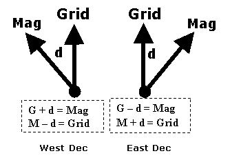
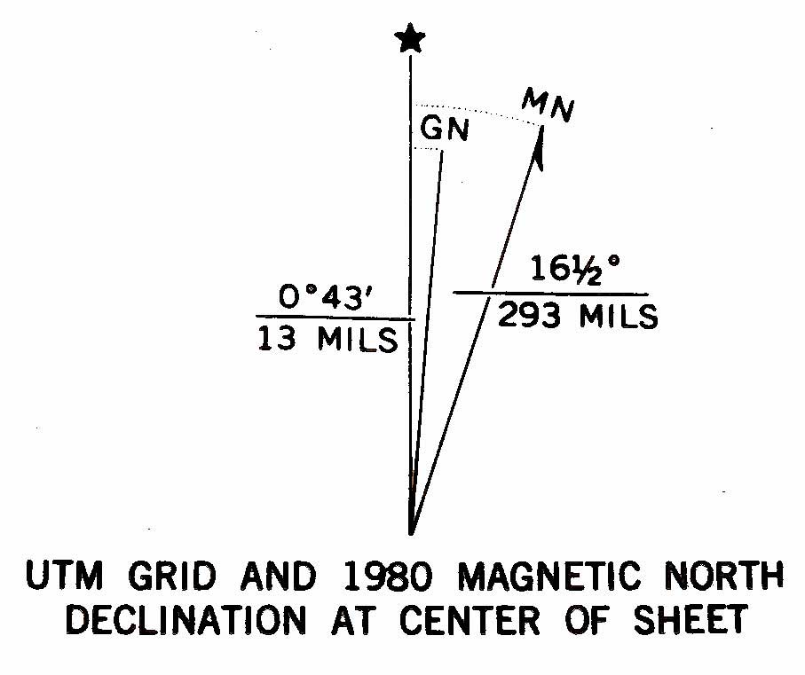
Diagram (2) Diagram (3)
Magnetic Declination Conversion Chart Example magnetic declination diagram from
a USGS map legend with a declination
of 16.5 degrees from True North
The procedure described below will work for both True North and Grid North on the map. Select the desired value and
treat as Grid in the calculations below.
To adjust for magnetic declination proceed as follows:
From the map to the compass you add westerly declination and subtract easterly declination to the bearing measured on
the map.
From the compass to the map you subtract westerly declination and add easterly declination to the bearing being
measured with the compass.
To help you remember the calculations the Basic Roamer AR© shows when to add or subtract the declination. Use
Diagram 2 in the following way:
If you were in a location with a declination of 5 degrees West, look at the West Declination diagram on the left of Diagram
2. If you were taking a bearing from the map of 125 deg that you needed to navigate using a compass you would say the
Grid bearing plus the declination (d) will give you the magnetic bearing (Mag).
Grid + d = Mag
125 + 5 = 130 degrees. You could then follow a bearing of 130 degrees using your compass.
If you were in a location with a declination of 5 degrees East, look at the East Declination diagram on the right of Diagram
2. If you were taking a bearing from the compass of 115 deg that you needed to plot on the map you would say the
magnetic (Mag) bearing plus the declination (d) will give you the Grid bearing on the map.
Mag + d = Grid
115 + 5 = 120 degrees. You could then plot a bearing of 120 degrees on your map.
As you can see, if you get the calculation wrong you may end up with some serious navigation errors. The Basic Roamer
AR© will help to minimize these errors by providing helpful diagrams and the calculations that go with them. This will take
the guesswork out of calculating the magnetic declination in any situation.
7. 1:24,000 UTM Grid
Using the Basic Roamer AR© to plot a precise location is very simple, for example,
Diagram (1) shows the Basic Roamer AR© in the correct position to show UTM grid 0,545,950-4,186,370 on a standard
USGS 7.5 minute map at 1:24,000 scale.
To try this for yourself, open the USGS map of San Francisco and find the vertical grid line number 0545 and the
horizontal grid line number 4186, place the Basic Roamer AR© onto the map using the 1:24,000 scale as shown in
Diagram (1) with the top right hand corner where the vertical line 0545 joins the horizontal line 4186. Now move the Basic
Roamer AR© along the horizontal plane towards the right (eastwards=easting) to a point which is 95 tenths from the
vertical grid line 0545. This will give you the first part of the reference 0545950, maintain this part of the plot by holding
the Basic Roamer AR© flat against the map, now slide it gently towards the top of the grid square (northwards=northing) to
a point that is 37 tenths from the gridline 4186, this will give you the complete UTM coordinate of 0545950-4186370, which
is the North support pylon of the Golden Gate Bridge in San Francisco. You can then use a fine pencil to draw a circle
around the plotted location using the 100 meter cutout circle of the Basic Roamer AR© The circle on the 1:24,000 UTM
grid is positioned so that when your fine pencil is used to draw the circle, the point of reference will be at the center of that
circle. This makes CP locations easy to plot and doesnÕt obscure important map detail at the point of interest.
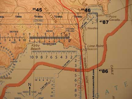
Diagram 1
8. Primary 1:24,000 UTM grid Without the 100 Meter CP hole
The top right hand corner of the Basic Roamer AR has a secondary UTM grid showing 200 meters of utm markings. This
secondary grid is very useful when the point to be plotted is in the first 100 meters of the grid and the markings are
missing due to the traditional hole that is used to mark CPÕs. Now you donÕt have to guess on the point to be plotted you
can use the secondary UTM grid on the corner of the Basic Roamer AR.
9. 100 meter diameter cutout on 1:24,000 scale
The 1:24,000 UTM scale has a 100 meter circle cutout that allows you to easily mark the location of points of interest. If
the UTM point is plotted correctly the point of interest will be in the direct center of the circle. The 100 meter circle
prevents the point of interest circle from obscuring any important detail close to the point of interest.
10. 1:63,360 UTM grid for 1inch to 1 mile maps
The secondary UTM grid on the Basic Roamer AR is a 1:63,360 scale grid that is set up for 1Ó to the mile maps. These
are large scale maps that often supplement the 1:24,000 maps. The UTM grid is used in the same way as the other scale
mentioned above.
11. 1.5 mile scale at 1:24,000
The top edge of the Basic Roamer AR has a 1.5 mile direct measuring scale. This scale allows direct measurement of
map distance at the 1:24,000 scale.
12. 1/10th mile distance measuring scale
This is a very accurate measuring scale that allows 1/10 of a mile distance measuring for the 1:24,000 scale.
13. Meters to feet/feet to meters conversion scale
This scale gives the navigator the ability to easily and accurately convert between meters and feet when required.
14. Miles to kilometers/kilometers to miles conversion scale
This scale gives the navigator the ability to easily and accurately convert between kilometers and miles when required.
15. 1:63,360 distance measuring scale Mile and 1/10th Measuring Scale
The left side of the Basic Roamer AR has a distance measuring scale for 1:63,360 map scales. This scale covers 4 miles.
16. 1:24,000 distance measuring scale
The Basic Roamer AR has 2 scales to measure distance. The 1/10th of a mile scale and the 1.5 mile scale on the top
edge of the navigation tool can both be used for distance measuring on the map.
17. Speed, time and distance calculations
The Basic Roamer AR contains the calculations required to compute speed, time and distance given 2 of the 3 pieces of
information. This is a useful reminder to save having to remember the calculations if required. The calculations are shown
below.
S = Speed
T = Time
D = Distance
S = (60/T) x D Speed equals 60 divided by Time multiplied by the Distance
T = (60/S) x D Time equals 60 divided by Speed multiplied by the Distance
D = (S/60) x T Distance equals Speed divided by 60 multiplied by the Time
These calculations are very useful if there is a deadline or time cutoff to reach.
18. Points of compass circle
The Points of the Compass overlay section of the Basic Roamer AR is very useful for determining direction to head from a
particular point of interest or CP. The overlay can be used to give an indication of the compass direction to follow.
19. Degrees of circle to 0 to 360
The Degrees of the Circle overlay is the quickest way to determine a compass bearing to follow on the map without having
to take out a compass. The overlay can be placed on the map and desired bearing can be read directly once the Basic
Roamer AR is aligned with the relevant North line.
20. 12 & 24 hour clock face
The 12 and 24 hour clock face is a simple reminder of the 24hour clock. This can be very useful when tired and confused.
21. Hole for neck cord
The Basic Roamer AR comes with a ready drilled hole for a lanyard or neck cord. This allows the Basic Roamer AR to be
kept handy at all times.
22. Helpful Basic Roamer© AR logo as Longitude and Latitude hint
The Basic Roamer logo is a useful reminder that you need to plot across then up or Longitude then Latitude.
23. Complete instructions on major features
The Basic Roamer AR comes with complete instructions for the major features.